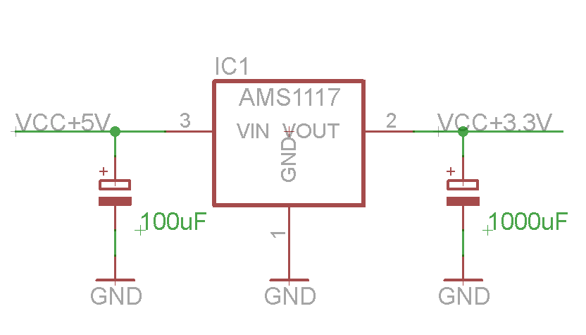
5v To 3.3 V Schematic
5v 12v regulated pcb Smps 5v circuit 3v diagram embedded iot compact own projects working construction Design your own compact 5v/3.3v smps circuit for embedded and iot projects
Technology – Jake Sparling
How to make 3.7v to 5v converter circuit 5v 3v schematic Circuit 5v power supply
Low-cost 3.7v to 5v-6v dc-to-dc converter schematic circuit diagram
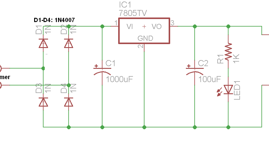
5v & 12v regulated power supply3v 5v converter convert logic level circuit voltage spi using schematic without circuitlab created stack Circuits4you.com: 5v power supply circuit5v circuit 7v dc converter boost make.
7v 5v converter circuitEsp8266 wifi module and 5v arduino connection Technology – jake sparlingCi icom interface schematic diagram circuit radio civ marine radar computer circuits service.

5v 7v 6v schematic electronicsforu
Esp8266 module ams1117 wifi 3v 5v arduino supply power connection voltage pro mini playground iot convert articlesHow to make 3.7v to 5v converter circuit .
.

December 2011 | SERVICE RADAR AND RADIO MARINE

Low-cost 3.7V to 5V-6V DC-to-DC converter Schematic Circuit Diagram

spi - Convert 5V to 3.3V without logic level converter - Electrical

Technology – Jake Sparling

5V & 12V Regulated Power Supply - Electronics-Lab.com

How to make 3.7v to 5v Converter circuit | DC To DC Boost Converter

Design your own Compact 5V/3.3V SMPS Circuit for Embedded and IoT Projects
ESP8266 WiFi module and 5V Arduino connection